|
|
The Work of Jagadis Chandra Bose – 100 Years of MM-Wave Research
|
|||||||||||||||||||||||||||||||||||||||||||||||||||||||||||||||||||||||||||||||||||||||||||||||||||
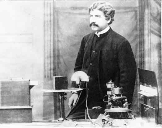 |
|
|
By about the end of the 19th century, the interests of Bose turned away from electromagnetic waves to response phenomena in plants; this included studies of the effects of electromagnetic radiation on plants, a topical field today. He retired from the Presidency College in 1915, but was appointed Professor Emeritus. Two years later the Bose Institute was founded. Bose was elected a Fellow of the Royal Society in 1920. He died in 1937, a week before his 80th birthday; his ashes are in a shrine at the Bose Institute in Calcutta.
 |
|
|
Bose's Apparatus
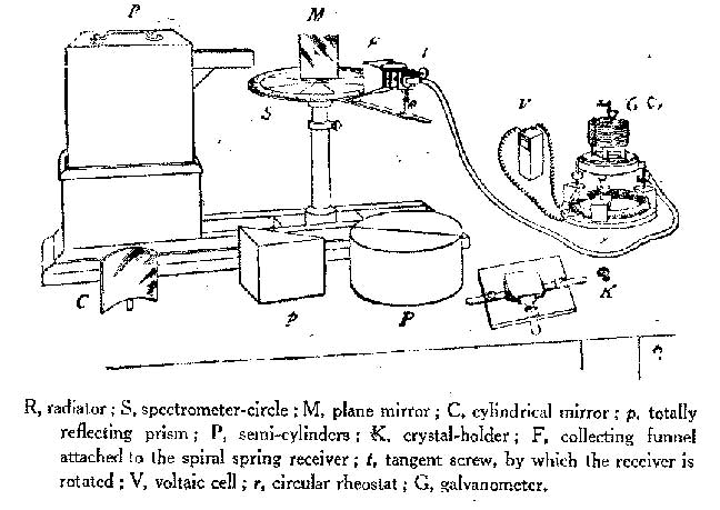
Bose's experiments were carried out at the Presidency College in Calcutta, although for demonstrations he developed a compact portable version of the equipment, including transmitter, receiver and various microwave components. Some of his original equipment still exists, now at the Bose Institute in Calcutta. In 1985 the author was permitted by the Bose Institute to examine and photograph some of this original apparatus. 3(a)
|
|
3b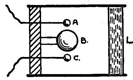 |
|
|
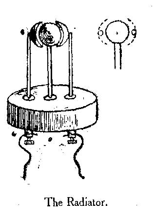
Figure 3 (a) shows Bose's diagram of one of his radiators, used for generating 5-mm radiation. Oscillation is produced by sparking between 2 hollow hemispheres and the interposed sphere. There is a bead of platinum on the inside surface of each hemisphere. For some experiments, a lens of glass or of sulphur was used to collimate the radiation - the first waveguide-lens antenna. The lens was designed according to the refractive index measured by Bose at the wavelength in use. Figure 3(b) shows Bose's drawing of such a radiator; the sparks occur between the two outer spheres to the inner sphere, at the focal point of the lens L at the right. Bose was able to measure the wavelength of his radiation with a reflecting diffraction grating made of metal strips [7].
 |
|
|
|
|
|
|
|
|
|
|
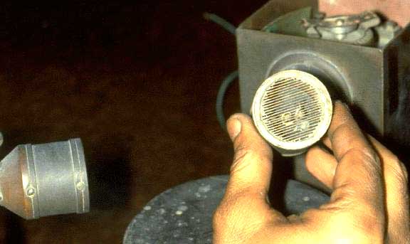
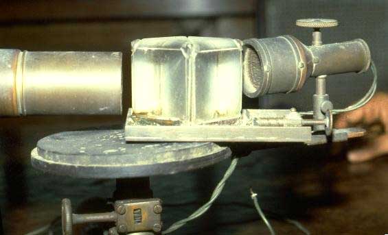
Figure 4(a) is a photograph of one of his radiating antennas; part of the spark oscillations are generated inside the overmoded circular waveguide. A polarizing grid is built into the antenna, clearly visible at the radiating end of the waveguide. Figure 4(b) shows a closeup of the dual spark gaps used for the transmitter; the sparks are generated between the 2 outer spheres and the inner sphere. Figure 4(c) shows both a transmitting antenna (left) and the receiver (right), with a dual prism in between set on the experimental rotating table.
 |
|
|
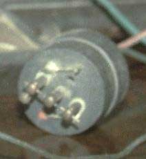
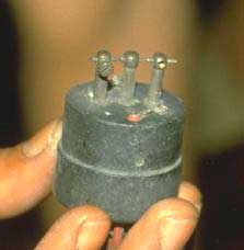
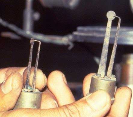
Figure 5 shows two of Bose's point contact detectors. In use, the detector would be placed inside an overmoded waveguide receiving antenna, very much like the transmitting antenna shown in Figure 4, and with a matching polarizing grid.
Bose measured the I-V characteristics of his junctions; an example characteristic curve of a "Single Point Iron Receiver" is shown in Figure 6. The junction consisted of a sharp point of iron, pressing against an iron surface, with pressure capable of fine adjustment. The different curves in Figure 6 correspond to different contact pressures. Bose noted that the junction does not obey Ohm's law, and that there is a knee in the curve at approximately 0.45 volts; the junction becomes most effective at detection of short wavelength radiation when the corresponding bias voltage is applied. He made further measurements on a variety of junctions made of different materials, classifying the different materials into positive or negative classes of substance. In one experiment he noted that increasing the applied voltage to the junction actually decreased the resulting current, implying a negative dynamic resistance [15].
 |
|
|
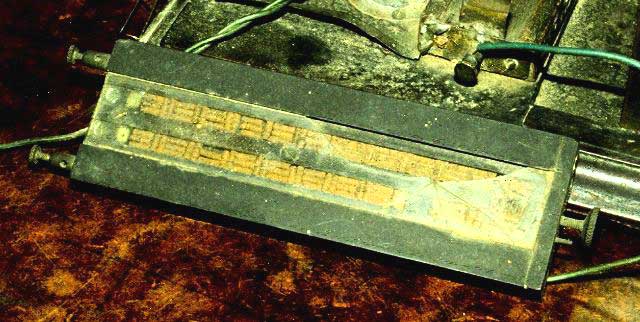
Another of Bose's short-wavelength detectors is the spiral-spring receiver. A sketch of a receiver used for 5-mm radiation is shown in Figure 7; the spring pressure could be adjusted very finely in order to attain optimum sensitivity. The sensitive surface of the 5-mm receiver was 1 by 2 cm. The device has been described recently [3] as a "space-irradiated multi-contact semiconductor (using the natural oxide of the springs)." A surviving, somewhat larger, spiral spring receiver is shown in the photograph Figure 8. The springs are held in place by a sheet of glass, seen to be partly broken in this example.
|

|
|
|
 |
|
|
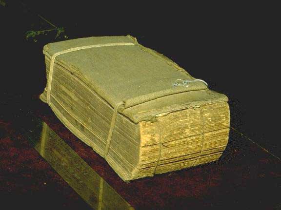
Figure 9 is Bose's diagram of his polarization apparatus. The transmitter is the box at left, and a spiral spring receiver ('R') is visible on the right. One of the polarizers used by Bose was a cut-off metal plate grating, consisting of a book (Bradshaw's Railway Timetable, Figure 10) with sheets of tinfoil interleaved in the pages. Bose was able to demonstrate that even an ordinary book, without the tinfoil, is able to produce polarization of the transmitted beam. The pages act as parallel dielectric sheets separated by a small air gap.
 |
|
|
 |
|
|
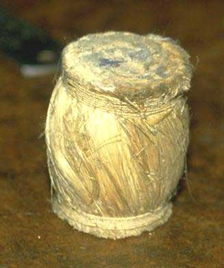
Bose experimented with samples of jute in polarizing experiments. In one experiment, he made a twisted bundle of jute and showed that it could be used to rotate the plane of polarization. The modern equivalent component may be a twisted dielectric waveguide. He further used this to construct a macroscopic molecular model as an analogy to the rotation of polarization produced by liquids like sugar solutions. Figure 11 shows Bose's diagram of the jute twisted-fiber polarization rotator, and Figure 12 is a photograph of a surviving twisted-jute polarizer at the Bose Institute.
 |
|
|
|
|
|
|
The Double-Prism Attenuator
Bose's investigations included measurement of refractive index of a variety of substances. He made dielectric lenses and prisms; examples are visible in Figures 1 and 2.
|

|
|
|
One investigation involved measurement of total internal reflection inside a dielectric prism, and the effect of a small air gap between two identical prisms. When the prisms are widely separated, total internal reflection takes place and the incident radiation is reflected inside the dielectric. When the 2 prisms touch, radiation propagates unhindered through both prisms. By introducing a small air gap, the combination becomes a variable attenuator to incident radiation; this is illustrated in Bose's original diagram, shown in Figure 13. Bose investigated this prism attenuator experimentally; his results were published in the Proceedings of the Royal Society in November, 1897 [8]. Schaefer and Gross [16] made a theoretical study of the prism combination in 1910; the device has since been described in standard texts.
 |
|
|
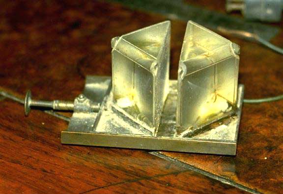
At the National Radio Astronomy Observatory in Tucson, Arizona a new multiple-feed receiver, operating at a wavelength of 1.3 mm, has recently been built and installed on the 12 Meter Telescope at Kitt Peak [17]. The system is an 8-feed receiver, where the local oscillator is injected into the superconducting tunnel junction (SIS) mixers optically. With an SIS mixer receiver the power level of the injected local oscillator is critical; each of the 8 mixers requires independent local oscillator power adjustment. This is achieved by adjustable prism attenuators. Figure 15 shows 4 of these 8 prism attenuators, installed on one side of the 8-feed system; this can be compared with Figure 14, which is a photograph taken at the Bose Institute in Calcutta in 1985, of an original prism system built by Bose.
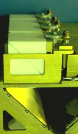 |
| Figure 15: Four of the 8 double-prism attenuators used to control local oscillator injection into the NRAO 1.3-mm 8-beam receiver in use at the 12 Meter Telescope at Kitt Peak. |
Conclusions
Research into the generation and detection of millimeter waves, and the properties of substances at these wavelengths, was being undertaken in some detail one hundred years ago, by J.C. Bose in Calcutta. Many of the microwave components familiar today - waveguide, horn antennas, polarizers, dielectric lenses and prisms, and even semiconductor detectors of electromagnetic radiation - were invented and used in the last decade of the nineteenth century. At about the end of the nineteenth century, many of the workers in this area simply became interested in other topics. Attention of the wireless experimenters of the time became focused on much longer wavelengths which eventually, with the help of the then unknown ionosphere, were able to support signalling at very much greater distances.
Although it appears that Bose's demonstration of remote wireless signalling has priority over Marconi, he was the first to use a semiconductor junction to detect radio waves, and he invented various now commonplace microwave components, outside of India he is rarely given the deserved recognition. Further work at millimeter wavelengths was almost nonexistent for nearly 50 years. J.C. Bose was at least this much ahead of his time.
Acknowledgements
I wish to thank the Bose Institute in Calcutta for help with material, and for permission in 1985 to photograph some of the original equipment of J.C. Bose, including the photographs shown from Figures 4 to 14 in this article. I thank Mrs. Nancy Clarke for help in preparing the manuscript.
References
[1] H. Hertz, Electric Waves. London: Macmillan and Co. Ltd., 1893. (Reprinted by Dover.)
[2] John F. Ramsay, "Microwave Antenna and Waveguide Techniques before 1900," Proc. IRE., Vol.46, No.2, pp. 405-415, February 1958.
[3] K.L. Smith, "Victorian Microwaves," Wireless World, pp. 93-95, September 1979.
[4] Lord Rayleigh, "On the passage of electric waves through tubes, or the vibrations of dielectric cylinders," Phil. Mag., vol.43, pp.125-132, February 1897.
[5] Oliver Lodge, Signalling Across Space Without Wires. Fleet Street, London, U.K.: "The Electrician" Printing & Publishing Company, 1908, 4th Ed., p. 83. (First edition published in 1894 under the title, The Work of Hertz and His Successors.)
[6] A. Righi, L'Ottica delle Oscillazioni Elettriche. Bologna, Italy: N. Zanichelli, 1897.
[7] J.C. Bose, "On the determination of the wavelength of electric radiation by a diffraction grating," Proc. Roy. Soc., vol. 60, pp.167-178, 1897.
[8] J.C. Bose, Collected Physical Papers. New York, N.Y.: Longmans, Green and Co., 1927.
[9] P. Lebedew, "Ueber die Dopplbrechung der Strahlen electrischer Kraft," Annalen der Physik und Chemie, series 3, vol.56, no.9, pp.1-17, 1895.
[10] Monoranjon Gupta, Jagadis Chandra Bose, A Biography. Bombay, India: Bhavan's Book University, 1952.
[11] Bimalendu Mitra, Sir Jagadis Chandra Bose: A Biography for Students. Hyderabad-Bombay-Calcutta, India: Orient Longman,Ltd., 1982.
[12] B. Mitra, "Early Microwave Engineering: J. C. Bose's Physical Researches during 1895-1900," Science and Culture, vol.50, pp.147-154, 1984.
[13] Photograph from Acharya Jagadis Chandra Bose, Birth Centenary, 1858-1958. Calcutta: published by the Birth Centenary Committee, printed by P.C. Ray, November 1958.
[14] G.L. Pearson, and W.H. Brattain, "History of Semiconductor Research," Proc. IRE, 43, pp.1794-1806, 1955.
[15] J.C. Bose, "On the Change of Conductivity of Metallic Particles under Cyclic Electromotive Variation," originally presented to the British Association at Glasgow, September 1901, reproduced in Collected Physical Papers, J.C. Bose, Ed. New York, N.Y.: Longmans, Green and Co., 1927.
[16] C. Schaefer and G. Gross, "Untersuchungen ueber die Totalreflexion," Annalen der Physik, vol 32, p.648, 1910.
[17] J.M. Payne & P.R. Jewell, "The Upgrade of the NRAO 8-beam Receiver," in Multi-feed Systems for Radio Telescopes, D.T. Emerson & J.M. Payne, Eds. San Francisco: ASP Conference Series, 1995, vol. 75, p.144.
| Privacy Policy | Terms of Use |
